

For What Purpose Is a Hydraulic Hose Press Used?
The hydraulic hose press is the machine that performs the pressing operation of the hose couplings in high tonnages by assembling the high pressure hydraulic hoses in the required lengths and connection types.
The hydraulic hose press is placed on the machine by choosing the appropriate size from the molds found according to the hose diameter to be used. Pressing of hydraulic hoses is carried out by adjusting the desired diameter on the machine.
Hydraulic Hose Pressing Instruction
Hydraulic Hose Stripping Instruction
The stripping length of the hose is calculated with the help of the chart below.
s
LS= Peel Length
L
LS = L – ( S+ t )
Peeling is done by measuring the end of the hose with a caliper at the peeling length determined by the knife. (For hand peeling)
See Hose Stripper Instruction for machine stripping.
HYDRAULIC HOSE PRESSING MACHINE CALIBRATION VERIFICATION INSTRUCTIONS
AIM:
It is aimed to ensure the operation of the Coupling Hose Pressing machines with the precision in accordance with the standards required in the production of Coupling Hose.
RESPONSIBLE:
Hydraulic Hose Team Leader / Staff
Production Quality Control Team Staff
Quality Control Manager
SCOPE:
It is aimed to check that the machines and devices used are at the desired sensitivity.
APPLICATION:
HYDRAULIC HOSE PRESSING MACHINE ADJUSTMENT TOLERANCE TABLE
Hose Diameter
3/16"
1/4"
5/16"
3/8"
1/2"
5/8"
3/4"
one"
1 1/4"
1 1/2"
2"
Tolerance Values (Max)
0 / -0.2
0 / -0.3
0 / -0.3
0 / -0.3
0 / -0.3
0 / -0.4
0 / -0.4
0 / -0.5
0 / -0.5
0 / -0.6
0 / -0.6
In the table above; In order to prevent dimensional errors that occur due to the stretching of the material while pressing the hydraulic hose union, tolerance values are given for each diameter hydraulic hose in addition to the union pressing measure in the electronically controlled union pressing machine.
While adjusting the hydraulic hose union pressing machine, the union pressing value entered on the electronic screen will not be adjusted outside the tolerance values given in the table.
According to the hose diameters in the table above, the calibration verification of the hydraulic hose union pressing machines should be done every 3 months. By measuring the hose union press values with a calibrating caliper, it is determined whether there is any deviation and the deviation rate is recorded in the calibration verification form.
If a dimensional deviation occurs outside the tolerance values given in the measurement controls, the values given in the table are selected according to the hose diameter and entered into the tolerance section of the machine.
The values given in the table above are the maximum tolerance values that can be entered for each diameter hydraulic hose.
In case the deviations in the tolerance ranges of the machine are out of the tolerance values of the responsible personnel working at the hydraulic hose union pressing benches, the team leader is informed by filling out a malfunction report form.
The team leader is responsible for ensuring that the machine is calibrated so that the machine can be readjusted to the above tolerance ranges after receiving the failure notification form.
HOSE LENGTH DETERMINATION INSTRUCTIONS
AIM:
To make accurate and safe determination of hose lengths.
RESPONSIBLE:
Workshop Staff
SCOPE:
Coupling Hoses
APPLICATION:
The lengths of the selected fittings are calculated according to the table below.
Since the hose will show some elongation during the pressing phase, the elongation length is added to the sum of the union lengths by referring to the table below.
The hose length is calculated using the formula below.
LH = Hose Length LH = LT-(L1 + L2 + S)
S =Elongation
L1 =1. Sleeve Length
L2 =2. Sleeve Length
LT = Total Length
HOSE COUPLING PRESSING SIZE CALCULATION INSTRUCTIONS
AIM:
To ensure that the calculation is done correctly when calculating the hose coupling pressing size.
RESPONSIBLE:
Coupling Hydraulic Hose Team Leader
Hydraulic Hose with Union Crew Personnel
SCOPE:
It covers the pressing process of all hose unions to be pressed to the hose ends.
APPLICATION:
When pressing the hoses with unpeeled sockets conforming to the hose diameter standards EN 853 1SN and/or EN 853 2SN standard, check the fitting pressing table. Hose fitting is pressed to the extent in the box where the hose type and the hose diameter coincide.
When pressing peel-off sockets in accordance with hose diameter standards and hoses in EN 856 4SP and/or EN 856 4SH standards, check the fitting pressing table. Hose fitting is pressed to the extent in the box where the hose type and the hose diameter coincide.
If pressing will be done with sockets that are not included in the hose coupling pressing table, the following calculation is used.
SYMBOL DEFINITIONS:
D = Socket Outer Diameter
S = Difference Between Socket Inner Diameter and Hose Top Diameter (For Non-peel Type Socket)
S1 = Difference Between Socket Inner Diameter and Hose Wire Top Diameter (For Peeled Type Socket)
d = Socket Inner Diameter
DP = Pressing Size
k = Embedding Dimension (Amount of Deformation After Space Between Hose OD and Socket Inner Diameter)
t = Hose Top Diameter (For Non-Strip Type Socket)
t1 = Diameter of Hose Wire Top (For Peeling Type Socket)
CALCULATING PRESSING DIMENSIONS FOR NON-PEEL TYPE SOCKETS
S = d-t
DP = D-S-k
Important Note: For “k” dimension, refer to the Table of Deformation Amount after the Space Between Hose Outer Diameter and Socket Inner Diameter.
CALCULATING PRESSING DIMENSIONS FOR PEEL TYPE SOCKETS
S1 = d-t1
DP = D-S1-k
Important Note: For the “k” dimension, refer to the Table of Deformation Amount after the Space Between Hose Outer Diameter and Socket Inner Diameter.
AMOUNT OF DEFORMATION AFTER THE GAP BETWEEN HOSE OUTER DIAMETER AND SOCKET INNER DIAMETER (k)
|
HORTUM CİNSİ
HORTUM ÇAPI
|
R1T |
R2T |
4SP |
4SH |
OL7 OL8 |
MT1 MTH1 MTK |
MT2 MTH2 |
R6 |
R13 |
TEFLON |
|
3/16”
|
1,6 |
|
|
|
1,2 |
|
|
1 |
|
1 |
|
1/4 “
|
1,7 |
2 |
2 |
|
1,3 |
1,5 |
1,6 |
1,2 |
|
1,2 |
|
5/16”
|
1,8 |
2 |
|
|
1,5 |
1,5 |
1,7 |
1,5 |
|
1,3 |
|
3/8”
|
2,2 |
2 |
2 |
|
1,7 |
1,7 |
1,8 |
1,6 |
|
1,5 |
|
1/2"
|
2,5 |
2 |
2,5 |
|
1,8 |
1,8 |
2 |
1,7 |
|
1,5 |
|
5/8”
|
2,7 |
2,5 |
2,5 |
2,5 |
2 |
2 |
2,2 |
1,8 |
|
1,6 |
|
3/4"
|
3 |
2,5 |
2,5 |
2,7 |
2 |
2 |
2,5 |
1,8 |
|
1,7 |
|
1”
|
3 |
3 |
2,7 |
3 |
2,5 |
2,5 |
2,5 |
|
3 |
2 |
|
1 ¼”
|
3,5 |
3 |
3 |
3,5 |
|
|
|
|
3,5 |
|
|
1 ½”
|
3,5 |
3 |
3 |
3,5 |
|
|
|
|
3,5 |
|
|
2”
|
4 |
3,5 |
3,5 |
4 |
|
|
|
|
4,5 |
|
|
2 ½”
|
4,5 |
4 |
|
|
|
|
|
|
|
|
Hydraulic Hose Press
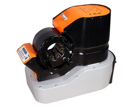
We manufacture hydraulic hose presses for many models you need for hydraulic hose manufacturing. Hydraulic hose press and Hose Cutting machine are produced in-house. With the Hydraulic Hose Press for your Hydraulic Hose Manufacturing needs, we provide quick solutions for your business, and solutions for you to prevent sudden and unplanned stops. Meet our Manufacturing Machine Park, which you need for hydraulic hose manufacturing, especially hydraulic hose press! We manufacture all the equipment that you can manufacture hydraulic hoses at your place. We install our Hydraulic Hose Press, Hose Cutting Machine, Hose Peeling Machine, Hose Testing Machine, Hose Marking Machine and Hose Packing Machines and provide detailed training to your technicians on this subject. You can reach all the machinery and equipment you need for the production of Hydraulic Hose from a single address.
Hydraulic Hose Press is Seide brand and Hydroscand brand.
Hydraulic Hose Press Types You Need to Make Your Hydraulic Hose Manufacturing. Do not make a decision without consulting us before purchasing a Hydraulic Hose Press in Hidroman!
Our Hydraulic Hose Press Types;
Hydroscand Brand Products
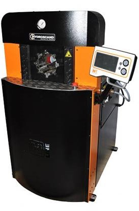
H120 Hydraulic Hose Press

With the H120 Hydraulic Hose Press, you are well-equipped for high-volume production in the field. The 300 ton clamping force and 155 mm clearance also allow for a wide variety of clamping applications. With CTS (color touch screen) control, the functionality of the crimper is extensive; storage capacity of many part numbers and die sets, easy search functions, easy calibration and much more. When extra options are not needed, the Basic version with only tightening, opening and diameter adjustment is preferred.
✓ Simple calibration
✓ Quick and easy to use
✓ User-friendly digital control
✓ Ergonomic operation
✓ Easy storage of molds
✓ Correct
✓ Reliable
✓ Very quiet
Simplicity is best in Hydraulic Hose Press!
Basic control is very simple with just the squeeze, release and teach button.
The "on position" is set by holding down the "teach button" position.
you want to open. The tightening diameter is adjusted on the micrometer screw.
Despite its simplicity, easy calibration and few
more are available.
CTS
Some features………
• Measurement or compression control.
• You need to login to operate, users are easily created on the screen. Signed in as a service
Allows full permission to change basic settings, service mode is password protected.
• Ability to save / load specific driving settings based on presets in the list.
• Logger for monitoring, completed folds logged with specific data, eg
current users, ride settings, order number etc.
• Four selectable languages: Swedish, English, German and French.
• Alarm list with open on fault indication.
• Instruction pictures as an aid for easy calibration and replacement of dies.
• Ability to scan part numbers.
• Ability to print orders/driving parameters.
• Counter for easy calibration / spin count.
• Counter for SPC testing.
• Service counter, time and spin count.
H120 Hydraulic Hose Press Technical Specifications
Clamping range in mm: 10 - 87 mm
Tightening range in inches: 0.39 - 3.42
Clamping force in metric tons: 300
Clamping force in kN: 3000
Maximum hose size in inches: 2"
Mold Set: H 32
Maximum die travel in mm: 70 mm
Master die Diam. /Length in mm: 99 / 97
Master die Diam. /Length in inches: 3.90 / 3.82
Machine control: Advanced Touch Screen control
Motor size kW 3-phase: 5.5 kW
Motor size in HP 3 phase: 7,5
Color: Black / Orange
DIMENSIONS
Depth: 800 mm
Width: 920mm
Height: 1500 mm
Models
H120CTS ED II: 9028-01-07
H120BASIC ED II: 9028-01-02
H120BASIC ED II 230v: 9028-01-03
Hydraulic Hose Press Die Sets
H32-10: 9060-32-10
H32-12: 9060-32-12
H32-14: 9060-32-14
H32-16: 9060-32-16
H32-19: 9060-32-19
H32-22: 9060-32-22
H32-26: 9060-32-26
H32-30: 9060-32-30
H32-34: 9060-32-34
H32-39: 9060-32-39
H32-45: 9060-32-45
H32-51: 9060-32-51
H32-57: 9060-32-57
H32-63: 9060-32-63
H32-69: 9060-32-69
H32-74: 9060-32-74
H32-78: 9060-32-78
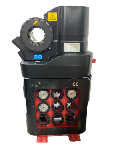
H32 Hidrolik Hortum Presi

H32 Hydraulic Hose Press Technical Specifications
Clamping range in mm: 10 - 87 mm
Tightening range in inches: 0.39 - 3.42
Clamping force in metric tons: 200
clamping force in kN: 2000
Maximum hose size in inches: 2"
Die Set: H32
Maximum die travel in mm: 33 mm
Master die Diam. /Length in mm: 99 / 80
Master die Diam. /Length in inches: 3.90 / 3.15
Machine control: Manual
Color: Black / Orange
DIMENSIONS
Depth: 400mm
Width: 850mm
Height: 530mm
Models
H32Basic: 9028-00-17
Hose Press Die Sets
H32-10: 9060-32-10
H32-12: 9060-32-12
H32-14: 9060-32-14
H32-16: 9060-32-16
H32-19: 9060-32-19
H32-22: 9060-32-22
H32-26: 9060-32-26
H32-30: 9060-32-30
H32-34: 9060-32-34
H32-39: 9060-32-39
H32-45: 9060-32-45
H32-51: 9060-32-51
H32-57: 9060-32-57
H32-63: 9060-32-63
H32-69: 9060-32-69
H32-74: 9060-32-74
H32-78: 9060-32-78

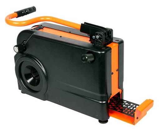
Manual Hydraulic Hose Press

We redesigned the concept from the ground up to make our smallest in-situ hose pressing machines more ergonomic. Carried like a briefcase, the weight of the hose press stays close to the leg, reducing the strain on the operator's back. During operation, the handle of the hand pump is placed at an angle of 90 degrees from the opening of the head to make the working position ergonomic. TRUE. Besides, the handle is bent to create a natural and ergonomic grip for the user. The dies are integrated inside the press which means no more mess with the dies.
The Hydraulic Hose Press is designed to suit the operator.


