


How to Test a Hydraulic Cylinder?
The traditional way to test the integrity of the piston seal in a double-acting cylinder is to pressurize the cylinder at the end of its stroke and measure any leakage through the seal. This is often called an “end-of-stroke bypass test.” However, the biggest limitation of the end-of-stroke bypass test is that it cannot detect ballooning of the cylinder tube caused by hoop stress.
In a previous post, I explained the danger associated with pressure concentration in a double-acting hydraulic cylinder. In this post, I will explain how to use the hoop effect to test the integrity of the piston seal in a double-acting hydraulic cylinder. However, before attempting this testing procedure, it is important to fully understand the danger associated with pressure concentration in a hydraulic cylinder.
The traditional way to test the integrity of the piston seal in a double-acting cylinder is to pressurize the cylinder at the end of its stroke and measure any leakage through the seal. This is often called an “end-of-stroke bypass test.” The biggest limitation of this test is that it cannot detect ballooning of the cylinder tube caused by hoop stress. The ideal way to test for ballooning of the cylinder tube is to perform a piston seal bypass test at mid-stroke. The biggest difficulty in doing this is that the force developed by the cylinder must be mechanically resisted, which may not be practical in the case of large bore, high pressure cylinders. However, a mid-stroke bypass test can be performed hydrostatically using the condensation effect. The required circuit is shown in Figure 1 below.
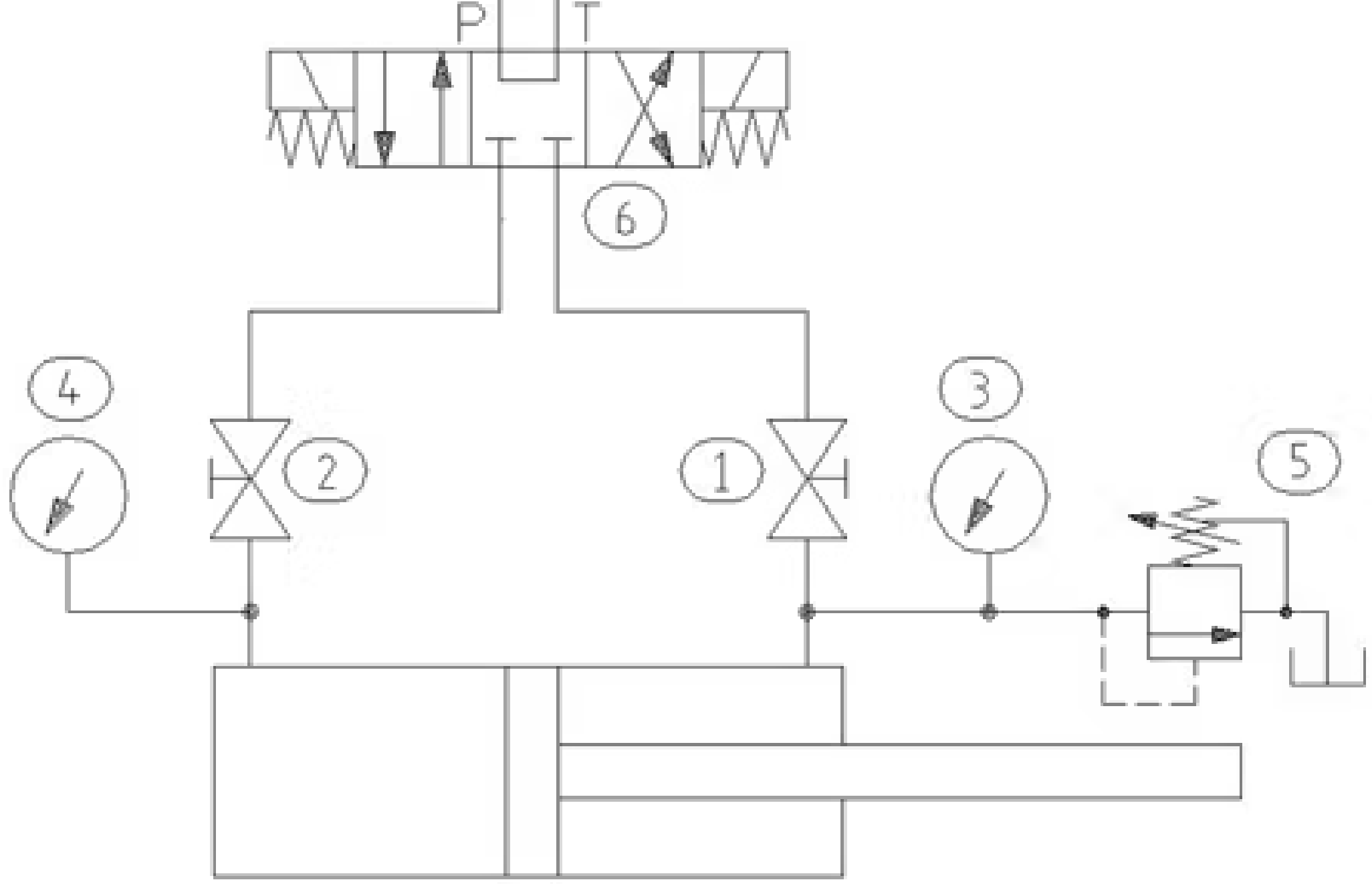
Figure 1. Hydraulic cylinder test circuit.
Test procedure
The procedure for performing the test is as follows:
Secure the cylinder with the service ports facing upwards.
Fill both sides of the cylinder with clean hydraulic fluid through the service ports.
Connect the ball valves (1) and (2), the gauges (3) and (4), the relief valve (5) and the directional control valve (6), as shown in Figure 1.
With the ball valves (1) and (2) open, tap the cylinder several times using the directional control valve (6) to remove all remaining air from both sides of the cylinder. Be careful not to "diesel" the cylinder.
Place the piston rod in the middle of the stroke and close the ball valve (2).
When the setting on the safety valve (5) is backed off, direct the flow to the rod side of the cylinder.
Increase the setting of the relief valve (5) until the nominal pressure of the cylinder reaches the value shown on the indicator (3).
Close the ball valve (1) and center the directional control valve (6). Note: The hydraulic power unit used to perform the test is assumed to have its own overpressure protection.
Record the corresponding pressure readings on indicators (3) and (4) and watch for changes over time.
If the effective area ratio between the piston and rod side of the cylinder is 2:1, and the rod side of the cylinder is pressurized to 3,000 PSI, the indicator (2) on the piston side should read 1,500 PSI. If the differential pressure across the piston is not maintained, this indicates a problem with the piston seal or pipe.
Under no circumstances should flow be directed to the piston side of the cylinder when the ball valve (1) is closed. Failure to do so could result in cylinder failure and/or personal injury. When performing this or any other hydrostatic (pressure) test, always wear appropriate personal protective equipment.