

How Does a Hydraulic Flushing Unit Work?
Flushing; The result of calculating the fluid in direct proportion to the pipe diameter, the max. It is the process of cleaning the particles in the pipe by circulating them through the pipes with flow rate.
With Flushing, the cleaning of hydraulic circuits is provided by removing all particles in the circuits above a certain size from the system. Cleaning of pipe lines is of great importance in systems using fluids. Studies have revealed that system malfunctions are caused by foreign substances.
Contamination in the fluid creates unexpected major failures and as a result production losses occur. This situation directly affects the production and maintenance costs negatively. The high frequency of the problem requires backing up hydraulic components, which increases the cost of stocking. Filter elements often clog and cause hydraulic oil to deteriorate in a shorter time. System performance drops.


Hydraulic System Cleaning (Flushing) Process:
Flushing is done after pickling. In this process, the pipes are connected to each other and the hydraulic oil used in the system is circulated through the pipes to be friction. The friction of the oil in the pipe occurs when the oil flow turns from laminar flow to turbulent flow. The flow change depends on the viscosity of the oil, the pipe diameter and the Reynolds number. When Reynolds number is 2320 and above, the flow becomes turbulent flow. The Reynolds number changes in direct proportion to the flow rate.
Flushing is very important as the biggest factor in the smooth operation of the system in hydraulic systems is the cleanliness of the system. Considering that the smallest particle that the best eye can see is 40 microns, we cannot see the particles that will cause malfunction with the naked eye. High particles can leak into the system through improperly assembled oil tank ventilation filters, pistons and other seals.
Oil comes into contact with all system components and should be perceived as important, just like blood in the human body. As a result, it is vital to maintain the machine components and oil performance at their best.
Flushing is done in two stages.
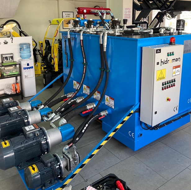
Stage 1 is made by adapting a unit of required size to the system from outside.
Stage 2 is done using the pump and tank in the system.
First cleaning process
The pipes are connected to each other and installed as a closed circuit outside or installed in a way to work in the system. Using a temporary pump and tank, a circulation circuit is created. Cleaning fluid (hydraulic oil) during the flushing process; The pipe circuit is set up as a closed circuit so that the system pump does not pass over the cylinders and valves by-pass. If there are pipes of different sizes in the system, separate cleaning can be done by grouping pipes with similar diameters.
Second Cleaning Process
It is the cleaning process by using the hydraulic tank and system pump of the hydraulic system by bypassing the elements in the hydraulic system (valve, cylinder, etc.). After the system is cleaned with the flushing unit, the main tank is filled with oil. All pumps are commissioned and oil is sent to the system at low pressure through the main tank. All blocks and lines are connected. Cylinders and hydromotors are not connected to the system, these lines are connected to each other by bypass. The point to be considered in this cleaning process is that the oil to be used in the cleaning process is the same as the system oil and that the materials to be cleaned are non-particulate. After reaching the desired values in the flushing process, the flushing circuits are disconnected and the system is brought into operation. In the meantime, the disassembly and assembly processes must be done carefully. Pressure test is applied as all lines are suitable for operation before the flushing process starts and no modifications can be made after the flushing process. Since the main pressure line and return line will be connected to each other in the flushing process, after the air is removed from the system, the rotation of the flushing unit is closed and the system is locked at 20 bar. The system is examined for 30 minutes to see if there are any leaks. After the return line is tested, only the pressure line in the system; Test Pressure = 1,5x Working Pressure Only the pressure line is tested. Flushing is started after the errors seen in the pressure test are corrected and tested again.
Flow rate calculation formula
Re = (21220xQ) / v x d
Q: Flow rate (lt / min.)
Re: Reynold's number
v: Oil viscosity (mm / sec)
d: pipe diameter (mm)
Flow rates should be determined according to the largest pipe diameter in systems. For example, if we take our biggest line as 2 ”(60,3-2,77); Its inner diameter is 54.76 mm. When the Reynolds number is 4000 and the oil viscosity is 22 mm² / sec at 60 ° C (140 F);
Q => 22x54,76 / 21220x4000
Q => 227 l / min.
The resulting flow is sufficient for flushing. The output flow rate indicates the minimum amount, and the flushing time will decrease relatively with higher flow rate. (It should be kept in mind that the main factor that determines the flushing period is the amount of contamination in the system, although it is a factor in the reduction of the duration.)


